FoxFlash comes with pin wiring diagram, open the foxflash manager install folder there is a folder called "Document".
The OTB pinout can be found in the document folder.
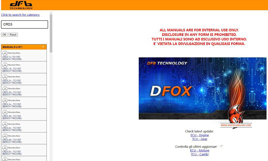
PDF format in "Help" folder or check online version via browser.

Search desired ECU type, for example Mercedes CRD3.20
You will see bench pinout
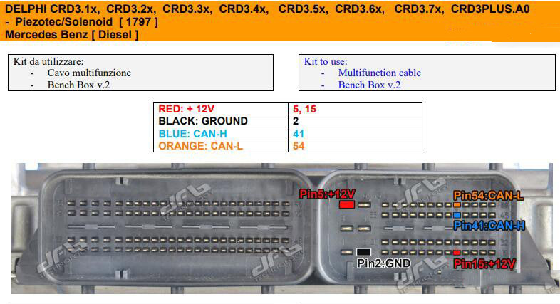
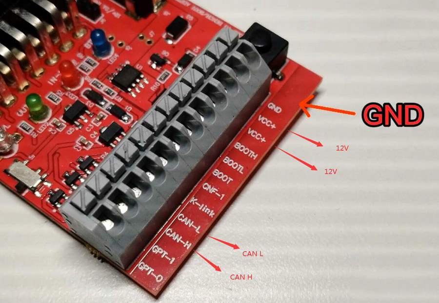
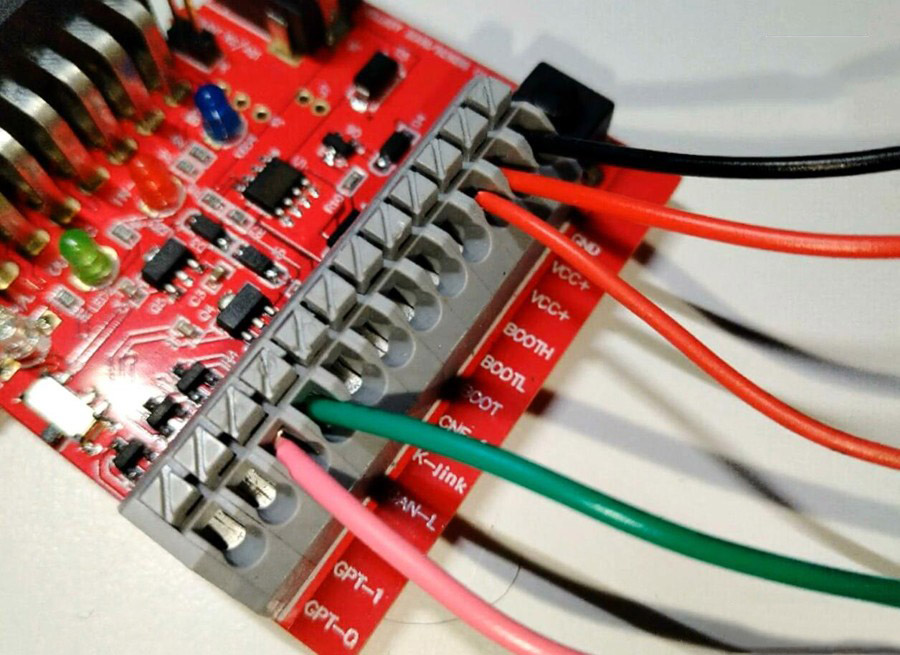
With OTB adapter, only need to connect GND, VCC, CAN H and CAN L.
Just check his CAN H, CAN L, VCC, GND then back to OBD driver connect with OTB. Don’t need to connect GPT.
If have Kline you also need connect Kline.
For example:
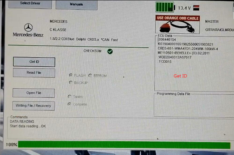
Foxflash read and write Mercedes CRD3.x via OTB mode
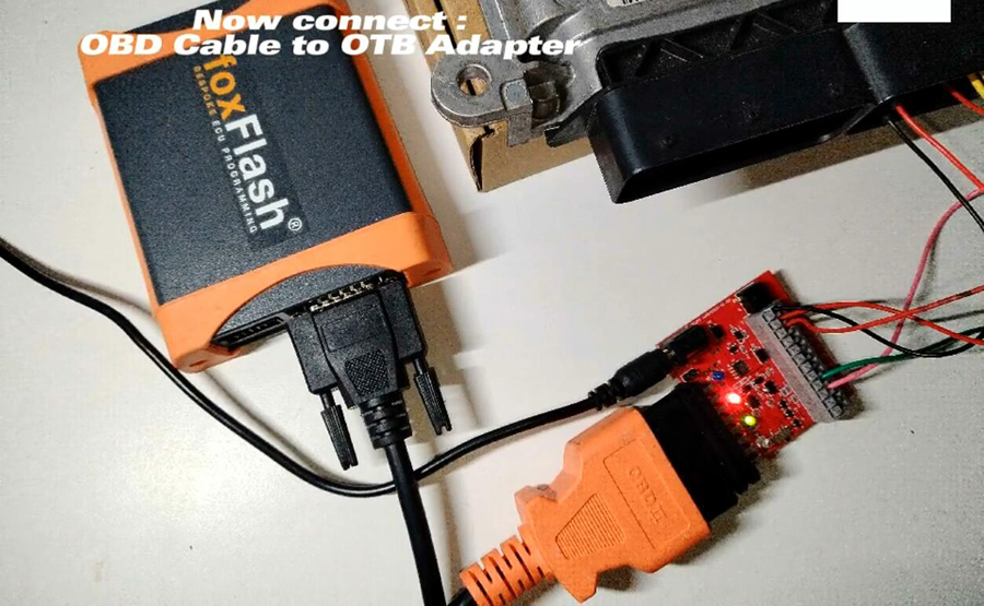
Connect to foxflash OTB adapter
Connect OBD cable to OTB adapter and add 12v power
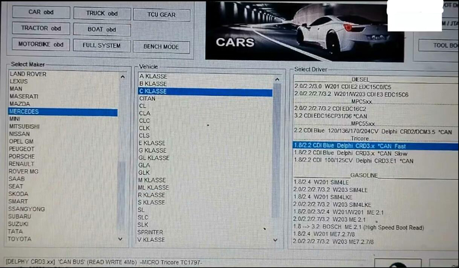
In foxflash car obd, select Mercedes then C calss, then CRD3.x
We will use the fast canbus driver