Need orange5 in-circuit wiring diagram for XC2361A-56 mcu in Airbag module BJ32-14D374-AC (2013 Land Rover).
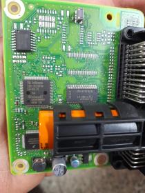
Here is the photo of the board attached.
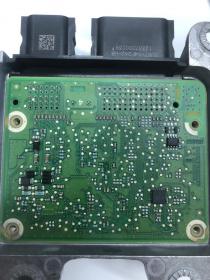
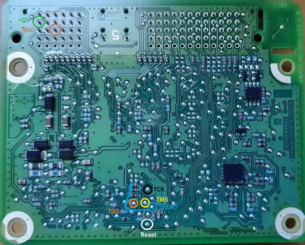
Here is the other side attached.
It is confirmed that RST and TRST and Reset are the same.
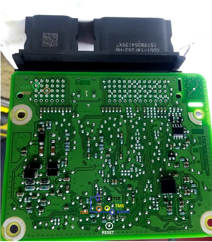
Here is two pinout diagram i found . They both looks like the same in regards to connection points for programmer.
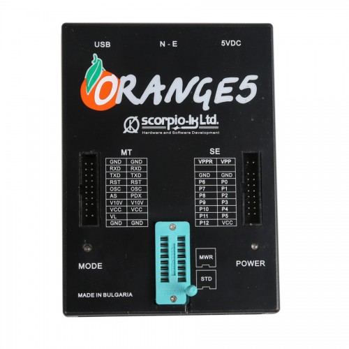
So here are the conversion from Orange5 to the pinout below.
Orange 5 Pinout diagram below:
GND GROUND
RXD TDI ( GREY)
TXD TDO ( ORANGE)
RST RESET (WHITE)
OSC TCK ( BLACK)
PDX TMS ( YELLOW)
VCC TO 5 volt ( NOT NEEDED FOR THIS MODULE)
If any problem, please re-check the soldering for the pinsout, also check the settings in the software, check usb port settings.
Note: Please apply 12 volt supply
Update:
The diagram provided are wrong .. you will end up bricking the ecu!!!
short ground to the board in 2 places
log1 needs connecting and lift up pins 60&62 from mcu
Anyway, you can refer to the label on Orange 5 device.
Any question on Orange 5 device, please contact at obdexpress.co.uk.