How to use Xhorse Multi- Prog Programmer to read and write microcontroller? Check the details below.
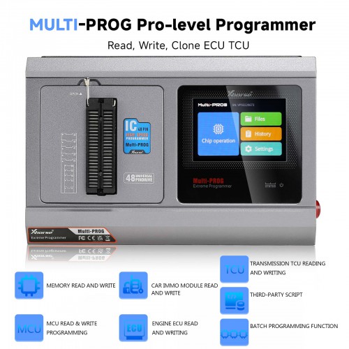
The microcontroller function is mainly used for data reading and writing of various automotive electronic modules and automotive computer modules. It is especially suitable for automobile circuit module repair. Before using this function, you need to understand some principles and common knowledge of microcontroller.
Multi-PROG supports reading, writing, and programming various common brands of microcontrollers. Before data reading and writing, you should make the correct wiring connections according to the software wiring diagram corresponding to the brand, model, and microcontroller series. For some models, the microcontroller requires soldering minimum system
circuit before reading.
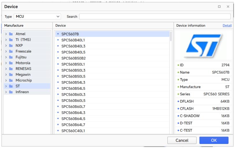
1.Microcontroller Manufacturer Distinction
The Xhorse multi-prog supports reading and writing microcontrollers from multiple manufacturers. Among common automotive electronic modules, the microcontroller
manufacturers used include Atmel, Motorola, Freescalo, Infineon, Renesas, STMicroelectronics, etc.
2.Microcontroller Memory Area Division
Microcontroller usually has three storage spaces: program area, data area and configuration area. The program area stores the program data of the microcontroller.
The data area stores the information data of the microcontroller. And the configuration area stores the corresponding configuration data of the microcontroller, such as the encryption byte option, the startup byte option, and so on. When reading and writing microcontroller data, it is necessary to distinguish by different areas. In software names such as FLASH, CFLASH, CODE, and ROM are usually used to represent the program area. The names such as DFLASH, EEPROM, DATA, INF, etc. are represent the data area. The names such as Config are represent the configuration area. Please note that the configuration area may be unreadable for encrypted chips.
The microcontroller option provides wiring diagrams for basic read/write of the corresponding microcontroller. During the actual read/write process, a multimeter is necessary to find the connection diagram for the specific board.
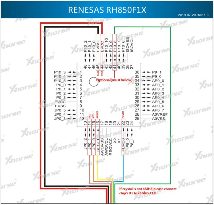
If the crystal frequency is not 4 megahertz, please connect pin 1 of the chip to the CLK output of the programmer: When reading, this pin needs to be checked whether it is necessary to connect an external clock pin for reading.
Learn more:
Xhorse Multi-Prog ECU/TCU Read & Write Operation Guide:
http://blog.obdexpress.co.uk/2024/01/02/xhorse-multi-prog-ecu-tcu-read-write-operation-guide/