Here we've collected maintenance solutions to some common problems of Lonsdor K518(K518ISE) Key Programmer. Read this article may help to fix those small issues.
Solution:
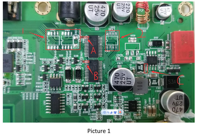
Power off the K518 device(K518ISE or K518S) and plug in the original power cable, thentest the voltage of each pin of the cable. The voltage of each pin is about1.5V to 3.5V (except cathode and power). If there is any pin of 5V to 12V(except power), probably there is a short circuit of some channel in thedevice. Remove those chips in Position U104, U105 and U103 in Picture 1(marked as Position 1 and 2) and check whether the voltage is normal ornot. If yes, theproblem is in those chips (Position U104, U105 and U103).If there is any pin of no voltage (except cathode), check whether the OBDcable works well first. If the cable works well, check whether there isbreakdown of No.ADG1406 in Position U107 and U108 and change chipsin corresponding positions.
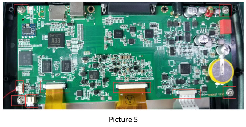
Chips will be burnt out due to improper operation and unstable voltageor current of vehicles. We need to alter the channel to avoid burningchips out. Power off the device and cut off the power first (showed inPicture 5), then take away the battery and the loudspeaker. Take awayscrews and loosen the socket. Take out the motherboard and put it in aninsulated place. Remove chips in Position U104, U105 and U103 andcapacitance (showed in Picture 1) (marked as Position 1 and 2). Use ablade to cut the circuit in Position A and B (the first pin from the left inPosition U108 and U109). Do not cut off too much. Do not cut out offPosition A and B (Do not cut the pins of the chip.).
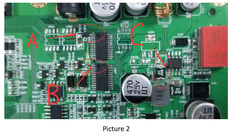
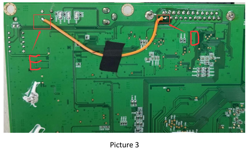
After that, the boardwill show as Picture 2. Weld a diode (No. 1N5819HW) in Position A. Weldthe cathode of the diode to the pin of the chip. Then use an electric wireto connect the first pin of U108 and U107. We need to cut the circuit inPosition C to cut off the power of vehicles, because the power of vehiclescomes straightly to this part via OBD. Picture 3 is the back of the PCBboard. The channel also needs to be altered. Use a soldering iron to weldPosition D and E, then the power of vehicles comes through Position E.
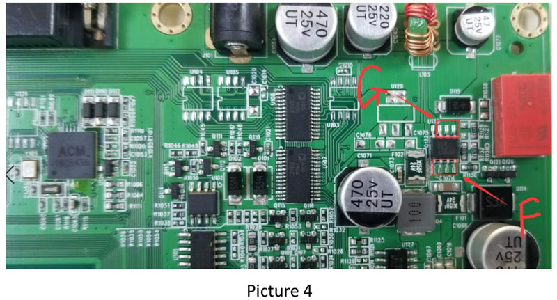
After welding, use a multimeter to check whether there is a short circuitin Position F in Picture 4 and Position D in Picture 3. If yes, the circuit isnot well cut. Then use a multimeter to check whether Position G inPicture 4 and Position D in Picture 3 are well connected. If not, Position Dand E in Picture 3 are not well welding; or the electric wire is broken.
After that, check whether the voltage of each outlet is normal. Do notcut other components when operating. Ask for remote guidance if youhave any questions.
Solution:
Solution:
Return to your Lonsdor seller for repair.
Solution:
Power on and off the device, then charge it for two hours. Checkwhether the charger can put an amount of charge into the device. If not,check whether the battery port in Position CN37 is loose or change abattery.
Solution:
Solution: Change WIFI module (No.RL-UM12BS-RTL8188EUS).
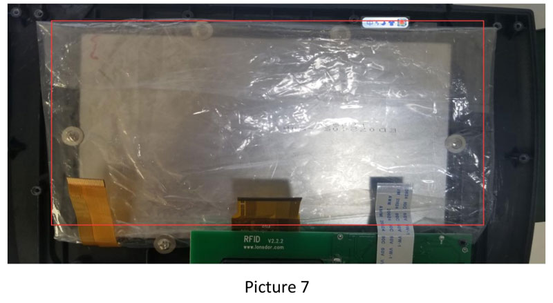
Solution: Change the touch screen.
Solution:
Solution:Check whether No.MB506 in Position U5 is broken.
Solution:Check whether the button flex cableis loose.
Solution:Checkwhether the slot in corresponding position is poor contact.
Solution:Check whether the cable works well.
Solution:Return to your Lonsdor seller for repair.
Solution:
Attention:
6 The article is forcustomers’ convenience. Please do notdetect and study the device when repairing. Or you are responsible for aseries of issues that arise. There will be accountability in seriousconditions.